Technology in focus: APFC and PSTs
July 22, 2024
There are many forms of power flow control solutions for transmission and distribution grids, but the differences between these solutions are often not well understood. In this article, Sarah Rozon presents two commonly known power flow control solutions—advanced power flow control (APFC) and phase shifting transformers (PSTs)—describing how they work, their main applications, and the differences and similarities between them.

Power flow control solutions have evolved significantly since series reactors and series capacitors were first deployed in the 1920s. In this article, I’ll focus on comparing a leading advanced power flow control (APFC) solution— SmartValve™—to a conventional form of power flow control: the phase-shifting transformer (PST).
What are APFC solutions and PSTs?
Advanced Power Flow Control (APFC) refers to modular power electronics-based devices that are part of the FACTS (Flexible Alternating Current Transmission Systems) family of devices. APFC solutions can dynamically control power flows on transmission and distribution grids by changing the reactance of the line on which they are deployed in real-time. See EPRI’s definition of APFC here. SmartValve™—a patented, single-phase, modular Static Synchronous Series Compensator (m-SSSC)—is the most well-known and widely deployed APFC solution. SmartValves are deployed as part of a SmartValve System where there is at least one SmartValve installed per phase. Given their modular, voltage-agnostic design, SmartValves can be easily and quickly added to existing deployments over time to scale the voltage injection output, and devices can be relocated if the network needs change.
In contrast, a phase-shifting transformer (PST) is an older form of power flow control equipment that is transformer-based and controls power flows by changing the phase angle of the voltage at the output terminals (compared to the input terminals); PSTs use an electro-mechanical tap changer to change the phase angle in discrete steps. PSTs have been used on transmission grids for decades to manage the large and consistent needs for power flow control, such as on high voltage transmission lines between countries. However, PSTs typically have long lead and delivery times because they require a bespoke design and significant civil works before they can be installed. In some regions, PSTs are more commonly known as quadrature boosters (QBs) or Phase Angle Regulators (PARs).
With rapid increases in electricity demand and use of inverter-based resources (such as wind and solar), the need for more dynamic (faster switching) power flow control solutions has become increasingly pressing. There are three important factors that may advantage APFC over traditional PST solutions: the flexibility to deliver solutions quickly, the potential to incrementally expand solutions, and the ability to defer investment decisions until an asset owner has more certainty on network needs.
SmartValve Advantages to PST
|
APFC |
PST |
Deployment flexibility | Modular, flexible solution SmartValves are modular voltage-agnostic devices that can be scaled to incrementally increase power flow control capabilities. Learn more about how to value this flexibility in network planning in my colleague Hedd Roberts’ blog | Fixed solution PSTs are fixed solutions and must be sized far in advance, which increases up-front capital expenditure and overinvestment risk. |
Controllability | Real-time, dynamic control SmartValves uses proven voltage source converter (VSC) technology that is capable of injecting a voltage in quadrature with the line current to synthesize a capacitive (- Ωs) or inductive (+ Ωs) reactance in a continuous range. This enables the system operator to incrementally and continuously change power flows on circuits in real-time depending on the system conditions. | Mechanical tap changes PSTs control power flow in discreet steps with mechanical tap changes. Mechanical tap changes are much slower than APFC voltage injection at controlling power flow. As a result, there are only so many PST tap changes that are possible post-contingency within the short-term (approximately 10 minutes). PSTs must be tapped pre-contingency, which limits grid flexibility and response to contingencies as well as incurs losses. Furthermore, PSTs greatly reduce the ability of the grid operator to respond to changing grid flows caused by intermittent renewable energy generation. |
Siting considerations | Flexible deployment options –SmartValve solutions can often be installed within the existing substation footprint, removing the need for land acquisition and permitting, which reduces costs and lead time. The SmartValve deployment layout is also optimized for the site to preserve space or expand the solution in the future. For example, ‘double-stacking’ can be done so that two SmartValve devices are deployed in the footprint of one unit. It is also possible to distribute SmartValves along a circuit or multiple circuits (push & pull) so that large solutions do not have to be deployed in one single location. | Significant space required at single location PSTs are bulky devices that require significant substation space at one single location, often necessitating the expansion of an existing substation or building a new greenfield substation. PSTs often also require special measures for transport to site which is difficult and costly for remote locations. The buswork to connect PSTs to the transmission line and PST oil containment measures also take up significant space. |
Lead & Delivery Time | 12 – 18 months SmartValves can be deployed within 12 to 18 months of ordering, meaning that they can be used to resolve urgent needs. SmartValves can be transported to site using standard transport equipment so no special permits are required which can delay projects. No road closure schemes, or specialized equipment are required. | Minimum 5 years PSTs can take upwards of 5 years to implement due to their bespoke design. PSTs can be challenging to transport, often requiring specialized equipment, permits and/or road closures. |
Redundancy | Modular system SmartValve Systems typically have more than one SmartValve per phase, which means that the loss of an individual SmartValve does not mean a loss of the total system capability. Each SmartValve has an integrated fast-acting bypass so in the event of a failure, it quickly goes into bypass mode and the rest of the SmartValves continue to operate. Additional SmartValves can be used as hot spares to quickly replace any SmartValves that require repairs to maintain high levels of system availability. | Single point of failure Conversely, the loss of one PST plant item is the loss of the entire PST. Without a spare PST, the full PST system would be out-of-service until the malfunctioning part is repaired. Recent cases in the US have taken over 6 months to fix. |
To illustrate the differences further, I’ll share two real-world examples of large-scale transmission projects where 1) a UK utility used SmartValves instead of a PST because they needed a modular, quick-to-deploy solution, and 2) a US utility will use SmartValves to extend the asset life of a PST at a critical grid seam that would otherwise be at significant risk of future component failure.
- The National Grid case: using SmartValves as an alternative to PSTs
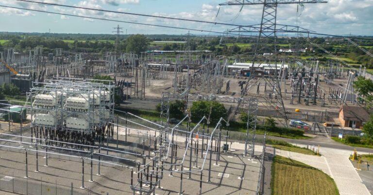
National Grid Electricity Transmission (NGET) are using SmartValves at 275 kV and 400 kV at three existing substations to provide power flow control across five circuits, unlocking 2 GW of extra grid capacity. Before deciding on this solution, NGET submitted several network reinforcement options to resolve the identified network need to the Network Options Assessment (NOA) which evaluates multiple solutions for the same network need to determine the option with the ‘least worst regret’ (LWR) across several scenarios. Alternate options evaluated included PSTs (or Quadrature Boosters as they are more commonly known in the UK) and other network reinforcements such as reconductoring overhead lines and transformer replacements.
As the LWR analysis values flexibility across multiple future scenarios, the SmartValve solutions performed well. They can be quickly delivered to meet the near-term network need and scaled up over time. The shorter lead time enabled NGET to defer making investment decisions until there was sufficient certainty on need, and resolve near-term grid issues while alternate options would still have been in planning or construction. This also avoided the risk of deploying an oversized solution that could have become a stranded asset in some scenarios.
The deployments at two of the substations were expanded in 2022/23 with additional SmartValves to meet an increased need for power flow control following the closure of a nearby power station. The original deployment had been designed to enable the easy scaling up of the projects so this expansion did not require any additional substation space, instead the additional SmartValves were safely installed ‘on top’ of the original devices. This would not have been possible if a PST solution was used instead.
- The VELCO case: extending the asset life of a PST
VELCO, a utility in Vermont, have experienced issues with a PST at their Sandbar substation connecting New York and Vermont state. This PST failed in January 2021, requiring a replacement PST to be moved over 60 miles and installed to provide power flow control later that year[1]. After two years of repair and maintenance, the original PST from Sandbar substation was returned to service at a different location, costing $3.5 M in total. The failure of the original PST was likely caused by excessive tap changes used to manage shifting power flows on the VELCO network. The shifting power flows were largely caused by the increased integration of intermittent generation (wind and solar) onto the grid.
VELCO predicts that tap changing requirements will continue to increase due to growing wind generation in New York State, which increases the risk of future PST failures. To prevent a future PST failure, VELCO chose to install SmartValves in series with the new Sandbar PST to reduce the number of tap changes on the PST by 99.8% (nearly zero tap changes anticipated) and provide 50% more power flow control capability. This solution also provides 50% redundancy so that the line can remain in-service after a PST failure.
The chosen alternative, adding SmartValves in series with the existing PST, is 16% less expensive than a series PST option and can be deployed in half the time. The SmartValve solution can also double its future output within the same footprint by stacking new SmartValves on top of the existing ones to fully replace the PST once it reaches end of life in 2032. Since SmartValve is a voltage-agnostic device, it will remain a suitable solution if/when VELCO decides to uprate the circuit to 230 kV in the future.
This project will be deployed in 2026 and is funded by the United States Department of Energy’s (DOE) Grid Resilience and Innovation Partnership (GRIP). GRIP funds projects that increase the flexibility, efficiency, and reliability of the US electric power system, with particular focus on increasing transmission capacity. For this innovative project, GRIP is funding 50% of the capital costs. Access the project’s factsheet here.
In summary, it’s clear that while both APFC and PSTs provide power flow control capabilities, they are quite different in terms of their flexibility, control, space required, and redundancy. There is already notable APFC adoption in the US, and it is expected to continue to grow due to new regulatory rulings like FERC Order 2023 and Order 1920, which require consideration of APFC in interconnection and transmission planning studies, respectively.
Federally funded programs like GRIP are further catalyzing APFC deployment. If you would like to learn more about any of the above, please contact us at info@smartwires.com.
[1] https://www.vermontspc.com/sites/default/files/2024-04/Sand_Bar_PST_Asset_Condition_VSPC_V1.pdf
Download our Factsheet now
Contributing expert
Sarah Rozon is Senior Analyst at Smart Wires, collaborating with North American utilities and government organizations to implement grid-enhancing technologies (GETs). Prior to joining Smart Wires, Sarah was an Engineer in Training at an electric distribution company, Hydro Ottawa, where she developed business cases for system renewal upgrades, devised 5-year business improvement strategies, and constructed system-wide reliability reports to determine system performance and prioritize asset replacement and renewal initiatives.
For press related purposes, please contact us at marketing@smartwires.com.
Dive deeper into related content
Explore our products and services
Talk to our experts


